Well things are going really well with the LED Website Indicator project. I re-wrote the firmware, this time using the amazing Autoconnect library (UI for managing MQTT broker and WiFi) and PubSubClient.
The new D1 mini and shield have arrived at the factory – along with a fancy new 3d print cover, so we uploaded the firmware and reached out to friends to test the WordPress plugin – in order to see some flashing lights. No lights. One friend even had his managed WordPress install locked (he wasn’t allowed to install new plugins, some sort of restricted mode – luckily a call to customer support resolved the issue quickly).
After a lot of troubleshooting I finally worked out the issue (on two different servers so far): the admins have locked down outgoing messages and closed most ports – including the one I’m using in the LED-SITE-INDICATOR WordPress plugin, port 1883. Long story short, we can’t have outgoing MQTT messages on all servers (it works on mine though).
So I had to re-write the PHP code as well, removing the MQTT and replacing with http call to an api – which then does the MQTT stuff, on my own server which is allowed.
The title says it all. Here are a couple of video’s to demonstrate the process:
Testing the version 5 ML model accuracy:
Testing the image recognition model
Deployed using temporary database:
I added a filter for different categories found by the machine learing model
Todo:
New images uploaded are not categorized – because I did the classification at home and just uploaded the database. I still need to get the image recognition to work on the server.
Scrolling is really not great, gets stuck sometimes and also new images loaded aren’t filtered.
Re-categorizing support – and support for more than one category per image
Remove bad images (or just hide them).
Refine the model to do better (“text-img” recognition isn’t great, for example).
I recently received a question via email which I thought might need a bit of answering – “Hello, may I ask how to convert the image into a bin file? I couldn’t find the source code on the website and look forward to your reply. Thank you very much.” Here is my response:
(tl:dr I didn’t share source yet but there are two ways to do it)
Great question! I haven’t been working on the file access much yet for the new MagicPoi. The hardware and getting the binary files is coming second to having an easy way to manage images – which I am spending most of my time on right now.
The Android app had a bug with creating .bin files which I never managed to fix, so I did update the “Smartpoi Android App” page to link to two PC programs which you can download – see the page here: https://www.circusscientist.com/smart-poi-android-app/ – just scroll to the bottom to see the (Linux Only) versions. These are easy-to-use drag-and-drop apps which will convert the image files to .bin format and also upload wirelessly to any connected poi. The .bin files are stored temporarily in a folder in the program files, I am sure you can find them there once you try it. I didn’t share the source because frankly the code is a terrible mess which even I am embarrassed about #messyprogrammer – I am getting better at this by the way, look forward to some documentation coming soon!
Incidentally the example PlatformIO sketch linked from the “api” section here https://www.circusscientist.com/magic-poi-api/ does exactly this, getting the list of 10 files and then using the /api/output endpoint to download .bin files – to the D1 Mini in this case – and then displaying them in 72px. I would have to check but I think maybe all .bin files are compressed to 72px.. yes I checked – currently that’s the default, with option to support any size (thank goodness).
All files which are uploaded using the magicpoi.circusscientist.com site are automatically converted to .bin files. The .bin files are simply compressed image files – with one byte representing one pixel in R3G3B2 format (in the case of MagicPoi I think I rotate them 90 degrees also for the line by line scanning).
To get any image .bin file from the MagicPoi site at the moment you can use a quick hack – if it is an image you uploaded yourself you have to “share” it for this to work. Then scroll down to where the original image is visible (on the “profile” page) – not the rotated version! Right click and select “Open image in new tab” or just “copy url” – then go to the new tab and copy the image name. Now use the name with “.bin” added on for the download api: http://magicpoi.circusscientist.com/api/output/ajzs2w1aczeq.jpg.bin
I’m sorry I haven’t really been working on the poi hardware and that side of the project. Like I said, I’m focusing right now on front end usability for the web interface. Soon there will be categories for the images, for example, and sorting.
Once the interface is working I will return to hardware and firmware – and also documentation and new features as well as proper api accessibility.
I hope my response answered your question. Everything is a work in progress, but there is progress.
I made a demo highlighting some of the features of the online MagicPoi software. Also included are some bugs, and my ideas for the future of MagicPoi. Check it out:
Computer generated patterns – let me count the ways.
C++ code on-device – a simple for-loop using FastLED’s “Palletes”
Processing code – on Android, streaming to poi.
– created using Processing “Mask”, the coloured parts of the image change colour to create an ever-changing image sequence. I also implemented a sound activated version which shows a pattern according to volume on different frequencies (“Beats”) and a static “Cylon” effect (“Zap Game”)
Similarly C can be used to stream generated patterns to the poi (see here).
I have experimented with AI generators using different prompts – for example: – These are from “Midjourney”
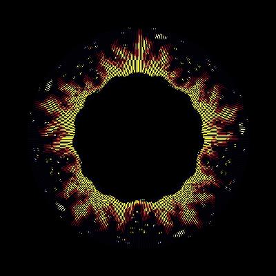
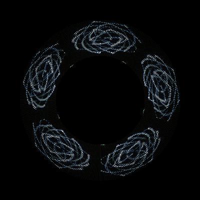
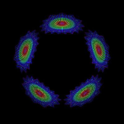
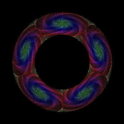
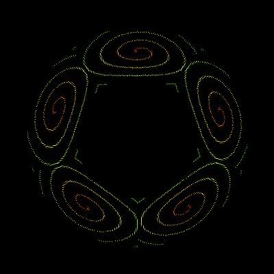
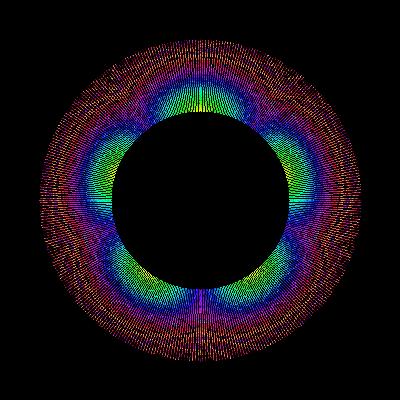
Finally, my current mission, using P5.js within the magicpoi website to generate pics with code. Examples:
Example:
The above example creates an infinite succession of 72x72px images – perfect for display on my 72px poi. I adapted the code from this showcase example on the P5js website.
My plan is to add this – and many more – options to the magicpoi website. They will complement the user generated images and be downloadable directly to the internet connected Magic Poi.
PS: Currently, if you want to see what any of the images generated above will look like on the poi, you can right click on the changing image, select “open image in new tab”, download the image and then on the magicpoi profile page (you need to be signed in for this to work – sign up, it’s free!) select upload and drag the image onto the page, or choose it from the file menu. Then you can turn this: into this:
As you can see, the possibilities are endless. I plan on making the P5.js image generation into a plug-in system for Magic Poi.
Currently the Magic Poi site relies on some Processing (Java) code which is called from python – as well as other bash scripts to do certain things. I wanted to make it faster and cleaner by using Python for everything, so I did some test scripts. (Github). Also, the Processing code required a virtual screen buffer to run on the server constantly!
The main functionality involves compressing images into the .bin files which are saved to the poi memory for display. Since there is limited memory, and to save bandwidth, I am using the R3G3B2 algorithm to compress images. The poi only accepts images which are rotated 90 degrees clockwise, so that needs to happen too, as well as dynamically re-sizing any images which are wider than the 72px available.
I am still conflicted about whether to keep the Android app as the control for the poi, or to do something else, but making everything available as an api on the server keeps it flexible for now. The RotateImageVisualPoiStyle api can be accessed right now. Upload your image, and see what it will look like on the poi!
# change the /path/to/image.jpg to your own image file name
curl --location --request POST 'http://magicpoi.circusscientist.com/api/rotate_visual_poi_style' --form 'file=@"/path/to/image.jpg"' --form 'fixed_width="72"' --output 'rotated_image.jpg'
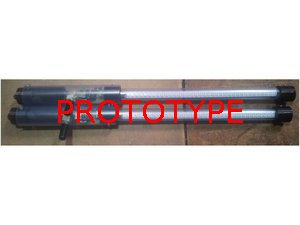
The factory where MagicPoi were being developed had a fire last month! All of the prototype poi melted, so all I have left is my breadboard version. This is going to cause some delays..
Updates:
The Magic Poi website now saves .bin files for every image uploaded. This is accessible via an api which I am working on accessing from the ESP32 and ESP8266. The .bin files are byte compressed images for display on the poi.
Example – list all shared .bin files on the server: curl http://magicpoi.circusscientist.com/api/get-filenames
One thing to note is that for testing purposes, all new .bin files are shared now. Please be aware that your images could be accessed (temporarily). This is because authentication is an extra step, so I’m working on the basic functionality first, with a public folder. The authentication works using jwt and I am having to access it from Java and C++. I already have a working Arduino test code which implements jwt correctly – security is important, so I want to do it right. One problem I already had to overcome is the fact that LittleFS file system has a limit of 31 characters for filenames (including path). The randomly generated filenames on the server are longer than this.
Not sure if I mentioned this before, the SmartPoi “Upload for offline use” option in the Android app doesn’t upload the whole image at the moment. I am not sure why, perhaps it’s something to do with the timing loop moving to the next image too fast. This option is going to be replaced by the web api anyway, so it’s not a priority, but I have compiled a desktop app which I use for converting and uploading (Linux only). You can get that for 36px here or 72px here – it can upload 20 images, just drag and drop your pics (need to be 90 degrees rotated, unlike the website) onto the window, connect to Poi AP and press “Upload”. You need to extract it and run from the command line but it should work on any Linux distro (tested on Ubuntu and Arch). At some point I will probably get annoyed at having to use my Laptop to upload images and fix the app though. Do email me if you need this for Windows, I might be persuaded to compile it for you using a VM if you ask nicely.
With the new APA102 2020 version being more available now, when Magic Poi is eventually launched it will have at least 100px, I’m thinking 128 is a good number but don’t quote me.
You may have noticed all of the hype around AI lately. A few years ago I used GAN with PyTorch to generate images for the poi (after training with around 100 poi pics, probably not enough). It was a big fail, but maybe it’s time to take another look. Would it be cool if you could just tell your poi what type of image you want to display, and it did it instantly? I do already have loads of Processing sketches I made to try and computer generate nice pics (some are on the Android App).
My K8 Prophecy clubs have reached the end of their tether. After 8 years of use! First of all, many thanks to K8Malabares for their excellent equipment. Most smartphones won’t last that long (except for my Samsung Galaxy S2, which still works). If you need juggling equipment you can’t go wrong with K8. I have some of their non-LED equipment as well and it’s just as good.
Upgrade
About six years ago I did an experiment – to see if I could emulate the K8 IR code on an Attiny85 chip. I knew they used that chip, or possibly the Attiny45, because one of my clubs was faulty and I opened it up to have a look – K8 sent a replacement, by the way, talk about great customer service!
Now that my balls and clubs are not working anymore, due to the battery reaching end of life, it’s the perfect time to test out my new code. Luckily K8 didn’t solder their chips, instead opting for a convenient chip socket for easy replacement! I made some updates to the code, adding new functionality and colours. (K8 have also done an update since I bought my equipment) The most important, for me, was adding a timeline record and playback. This means that I can record the timed colour changes for my entire show into the chip via IR remote, and play it back (in time with the music) by pressing a single button. This is similar to how Aerotech Ultimates used to work.
The batteries were the main thing. K8 use lithium batteries with 250mah power. I found some batteries online with a capacity of 600mah which I thought I could make fit (see below for details – not quite, but I made it work). I also bought a cool new charger for the new batteries.
The procedure
For anyone who wants to try and do this, I am posting some tips and photo’s.
1. Taking apart the club
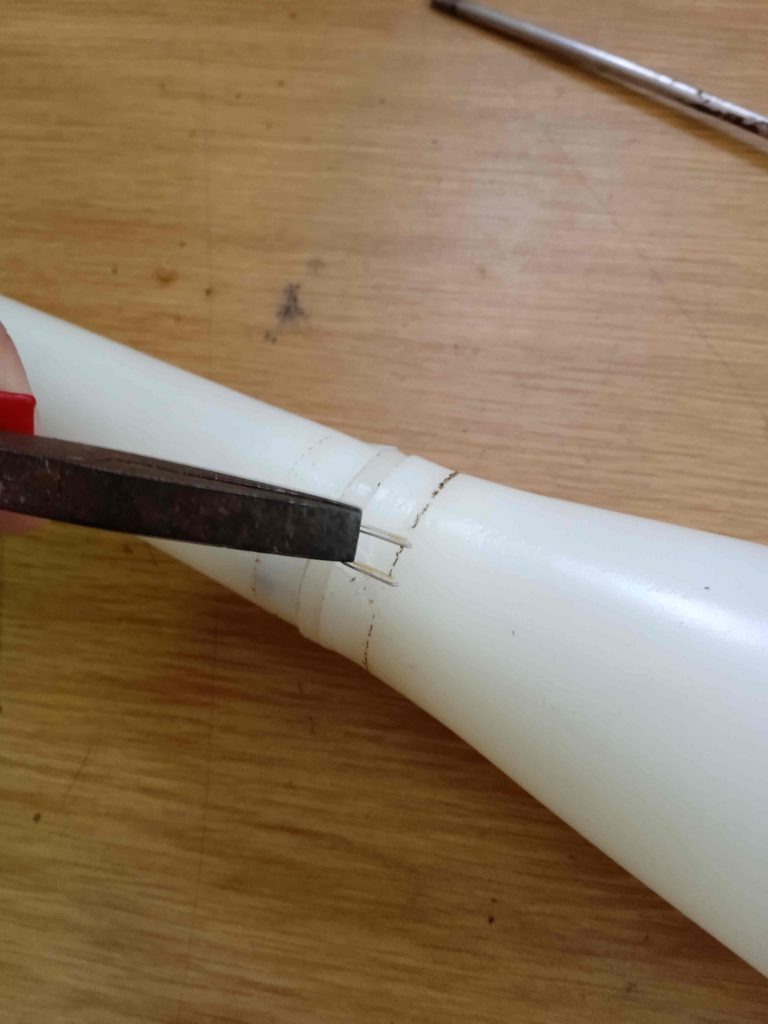
Pull off the tape from the center, then pull out the staples:
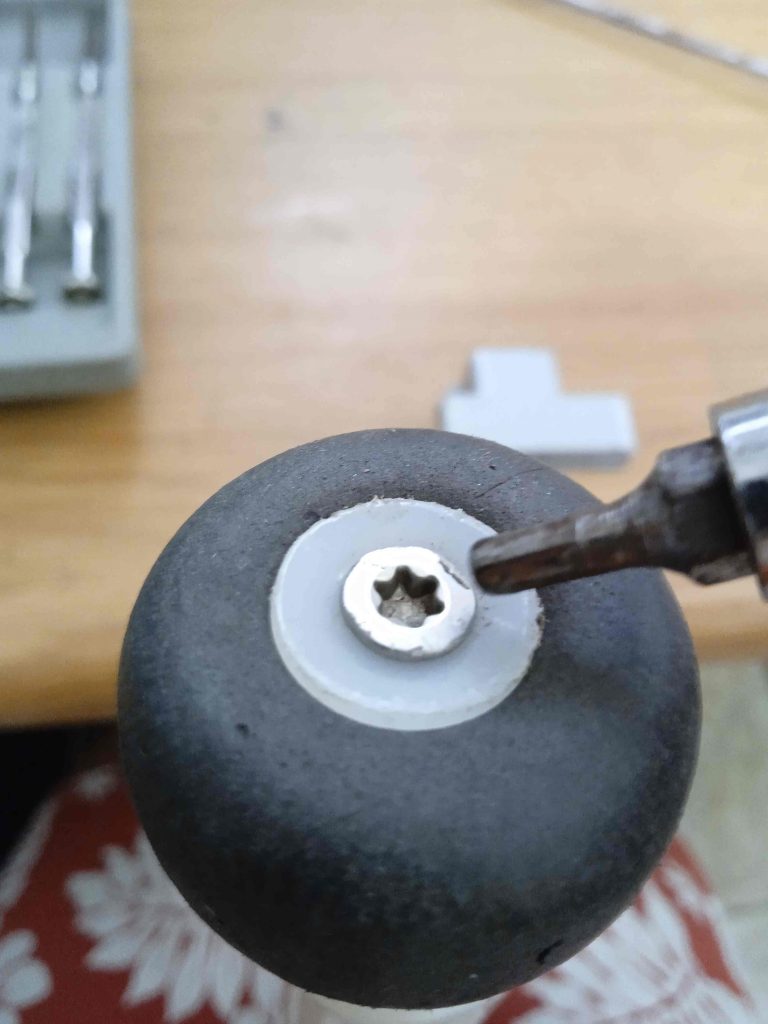
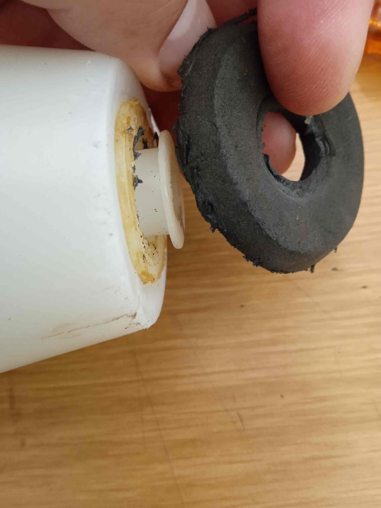
Take off the knob and top bumper:
Pull off the plastic around the handle, then unscrew the plastic spacer (needs an allen key)
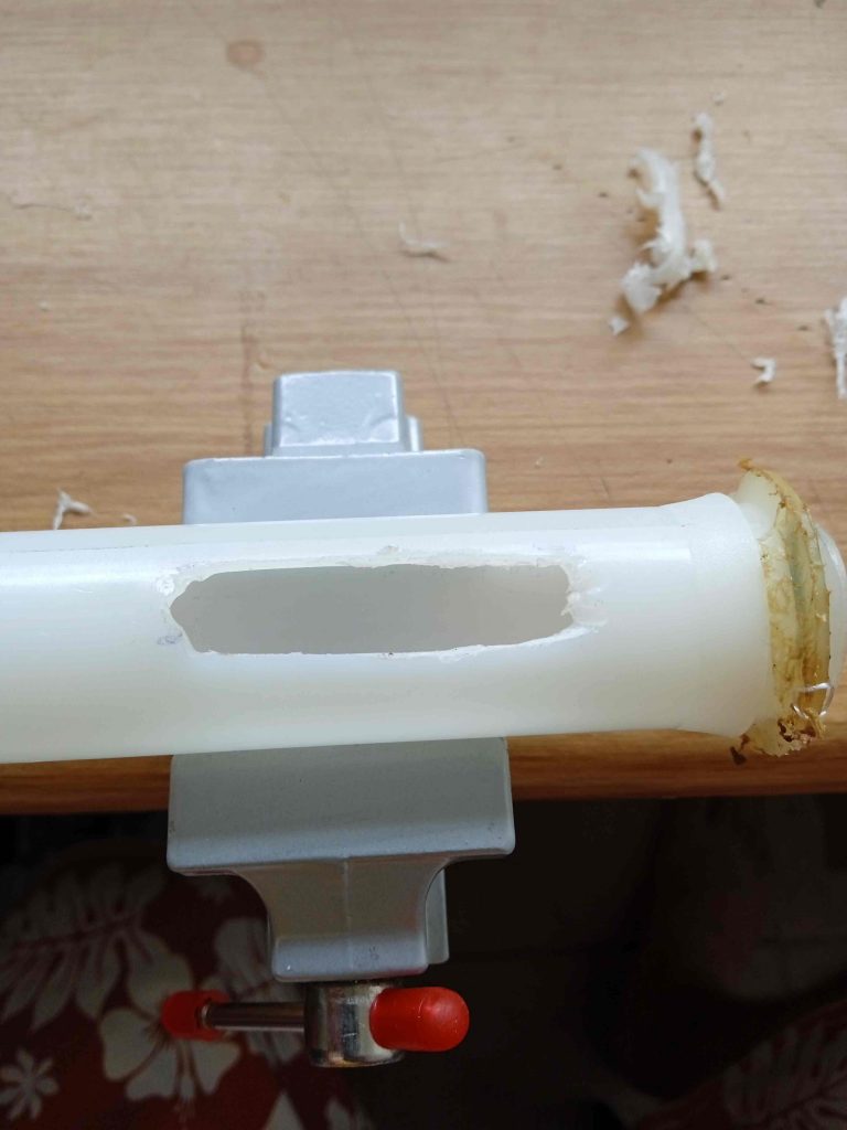
The next part is really sensitive – make holes in the top of the bulb cover to let the inside pipe come out. Get it out by pushing from the bottom – I also shoved a dowel inside and pushed upwards. If you use too much force this plastic pipe could bend, so be careful.
Now pull out some more screws holding the thicker top piece of the inside pipe on, and pull the spacer out to let the electronics out.
The bottom thin pipe should come off easily, leaving the bare circuit board.
Now cut off the insulating cover, exposing the battery. See how fat it is!
Pull the battery away from the board (carefully) and cut the two wires as close as possible to the battery – we need those!
The new battery ready for placement. Also, my newly programmed chip in place (old one from K8 labelled C2.
Now comes the hard part. Making space for the new battery. I had to cut into the larger diameter tube on both sides so that this could fit. I actually bought a Dremel to do this job.
Now put the circuit back into the top pipe, and find the battery wires. Then solder the battery on – finishing with insulation. The battery should fit with only a little bit sticking out on both sides of the pipe.
I used clear tape to stick the battery in – it was already pretty snug as the holes were just right.
Putting it back together
Just like taking it apart, only in reverse (and much easier)
Put the longer circuit cover tube back in and line up the holes (with the spacer), then put the screws back in. This works fine with just pliers, just twist left and right for these, while pushing in firmly:
Now the inside tube goes back into the top of the bulb – it just snaps in easily (how hard was that to take out, though, whoah!)
After putting the top bumper back, the middle spacer goes on. I forgot to mention, that doesn’t come off without removing a plastic screw cover (yellow, bottom of thin tube) so keep that in mind if you haven’t taken this apart yet.
Finally it’s time for the wrapped plastic handle – I didn’t put the staples back, you are welcome to try and do that..
Add some tape to keep everything together, screw on the knob and your club is “as-new” again.
Just a quick tip, I noticed that there is a bit of wear where the circuit goes from thin to thick (you will see what I mean – the long bit with all of the LED’s. Some of my clubs had non-working colours due to this, and I had to bridge the gaps with wires.
Let me know if you have K8 clubs and are interested in upgrading yours, I am happy to answer any questions.
Magic Poi, with the firmware written in Platform.io and the web interface in Flask is the future. Currently I don’t have a working set*, though, and due to upcoming shows I needed to make some changes to the existing Smart Poi.
*Due to other commitments, the company who are doing the hardware design for me have put the build on hold for now.
Updates:
LiPO batteries instead of NIMH
I have resisted using LiPO batteries for my projects up until now, but since I was already getting some for my K8 equipment upgrade I bought some 1000MAH LiPO batteries for the 32px poi. The voltage regulator I have in the circuit (LM117) is not optimal for these, I believe that it is not using the batteries full capacity – but it does work!
Quick uploading of offline patterns
At the time I wrote much of the Android app which pairs with Smart Poi (in 2017!), I was set on having all of the patterns stream from the smartphone to the poi over WiFi. In the real world unfortunately I found that due to WiFi interference this was not possible at most venues, where the 2.4GHZ spectrum is saturated and the stream stutters. So I made a way to upload and display patterns directly from the ESP8266 flash. Initially this was done with UDP as the streaming was taking place, then I moved over to http post. The latest update to the app disables UDP while the post is being sent, so uploads are really fast. I hope to refine this and port to the 72px version as well in the near future. You can get the apk for the latest version (so far only tested on Android 10) here – any future updates will be made to the same file. *Please note that the text message option still crashes, I am looking at this as a matter of urgency!Also, on first run the app sets up some example images and may need a restart (possibly even a phone reboot) to work correctly.
Magic Poi Lite version
I am working on a ‘lite’ single colour version of “Magic Poi”. The plan is to eventually replace all of my juggling equipment with internet enabled equipment which can sync using a web interface, like “Magic Poi”. The first test page is up here: http://magicpoi.circusscientist.com/lite and includes a colour change function and a really cool “Automatic Poi Simulator” visualisation which was kindly shared with me by Danny Thomas from kaien.com. Eventually this page will have a timeline (to music) function, and ability to download to the equipment. The firmware will also include offline capability, which will disable the WiFi to save power during operation.
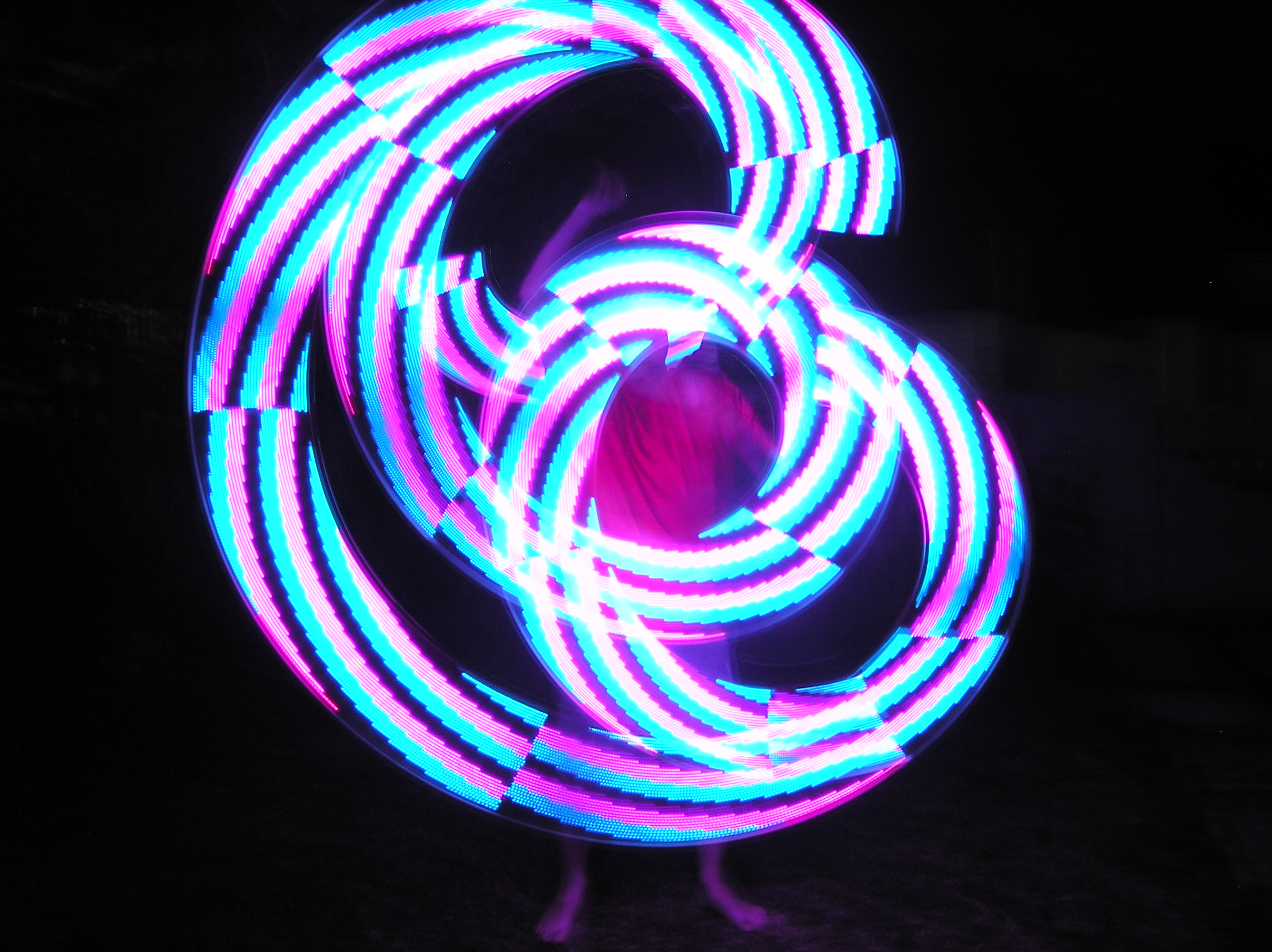
Many thanks to all those who continue to support this project. Smart Poi continue be a part of my performance every week. I’m inspired by the thought of enabling more people to make reasonably priced POV poi and other LED equipment which can do as much as, or more than the commercial versions.
As always, if you haven’t already, head on over to the Smart Poi Overview page and sign up to the newsletter for occasional progress updates. Feedback is welcome.
PS: did you know that every time someone visits my website, an LED flashes on my desk? I made an online service and open source firmware for the D1 mini which means that almost anyone with a website can have the same functionality. Check out https://www.circusscientist.com/led-website-indicator/ if you are interested!

 into this: