Time for some Poi Sync

The esp8266 is an amazing chip. On my poi the Master* poi creates a wireless access point which the Slave* poi connects to – and Android app connects as well, in order to transmit images. No router needed, just switch on poi, 2nd poi connect automatically, connect phone and start sending pictures.

*I have designated these names, for descriptive purposes.

There are limits, however. The ESP chips have a limitation of 4 connected devices per access point device. If you want more devices talking to each other you need a Router to handle the traffic.

This is fairly simple using arduino examples but it brings up configuration issues. I wanted my poi to be able to be used in standalone as well as Master-Slave-Android configuration, and now Router-Multiple-Poi-Android as well. A few settings are in order.

The first option, standalone poi without wireless, I configured directly in the loop() of code. If no wifi signal has been received within the last 5 seconds the poi switch to backup images. Great, if my phone’s battery dies the show still goes on.

The second alternative (Router) is a bit harder to organize. First, there is a limitation where the chip has to be told if it’s in Access Point mode or not on boot. Ok so that’s a setting. Then we need to know what the static ip address is (hard coded but configurable via web interface) so that we don’t conflict with other poi. Also, once you are in Router mode, what if there is no router?

Right now, my poi check a web configurable EEProm switch on boot first, for Router mode on/off. If Router mode is on, the poi enter connect mode. If, after a certain amount of time, the router is not found, the poi restart in Access Point (master-slave-android) mode. However, upon rebooting again they revert back to Router check, so one has to manually set back to Access Point only mode if required.

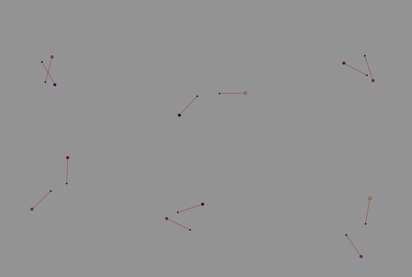
I need a diagram here to really show what’s happening.

The problem came in if the router wasn’t configured correctly, or was simply not available, the poi needed a reliable way to get configured. My poi get configured by web interface (local network, no cloud) so AP mode was needed by default in case things went wrong.

Here is the note from my code:

//to activate in browser: http://192.168.1.78/router?router=1

//to deactivate: router=0

So I just type it in the browser on my connected Android or PC and the poi are set. I will assign this to a button on the app at some point.

Currently the only option for multi-poi is to send the same image to all poi simultaneously (only 3 pairs, that’s all I have). This looks great, but there is much more to do obviously. Just a matter of code

Time to go play a bit with the toys…

Simple D1 mini Circuit

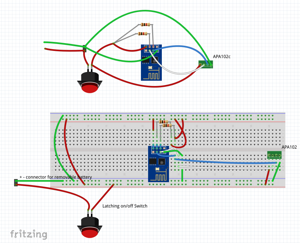
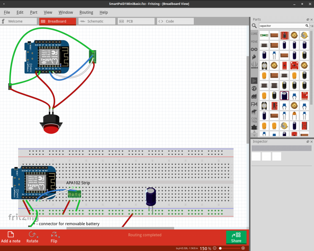
Although the Smart Poi is based on ESP-01 for size reasons, I find it easier to use the excellent D1 mini for testing. Here is the basic setup:

Notice that the D1 mini is powered from a battery source (4 x NiMH AA in series). This is not entirely necessary, you could get away with plugging in the D1 mini via USB, and connecting the APA102 strip to the 5v pin. The problem comes in when the LED strip starts drawing too much power, you will have dropouts in Wifi connectivity, or wdt resets and won’t know if it’s the code or just power.

Use the offline code from my Github repo to get started:

SmartPoiOffline code

This code works fine on other Arduinos as well as ESP8266 chips. Just change the pins.


Smart Poi Emulators

Two emulators are featured here, the first takes all images in a folder and shows them in sequence, as they would look on the spinning poi:


The second program receives RGB values from serial connected poi chip and displays on screen. This is showing what is actually being sent out to the LED strip, useful for testing – I was getting a bit tired of spinning the poi whilst programming them and the Android transmitter app at the same time.

The image below is of the computer generated default offline patterns, but if wifi sent images are available it looks somewhat similar to the above. Colour is not yet optimized.


For the serial sending to work on the poi, a fairly large change in code is needed. The serial necessarily slows everything down drastically, so it’s for testing only.

What it’s really like to be a developer

The long road to Smart Poi, visualized:

In order to make this video I used a program called gource. It takes your Git commits and creates an infographic video automatically. I modified the programmer avatar using the –default-user-image setting.  If you want to see something spectacular, check out the linux kernel gource!

Smartpoi is open source

I am working towards opening up the whole thing, hopefully I can get some productive feedback this way. However, to make something for yourself is one thing, to share is another. Lets just say the code is not ready to be shared. #messyprogrammer a lot

In the meantime here is a simple POV example on github which will work for esp8266 connected to an APA102 144 strip (36 LED’s only for testing). Don’t forget to add a cap between +5v and GND.

SmartPoiOffline

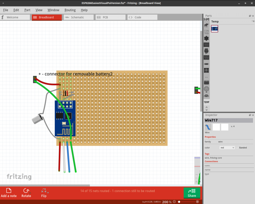
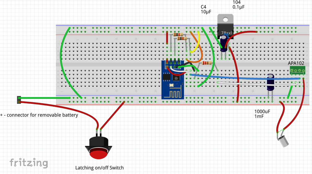
Here is a test board I made up, you don’t need the whole lot, just one of the esp breakouts and the LED strip. Here I have 2 controllers (only one on at a time!) and also a voltage regulator, and accelerometer as well.

In case you are wondering, the Esp-01 is connected to the breadboard by this method: http://www.instructables.com/id/Making-ESP8266-01-module-breadboard-friendly/

Simply put, you remove the plastic pin spacers with plyers, and now the pins are bendable to a more breadboard friendly configuration. No soldering needed.

INTRODUCING SMART POI

Smart Poi, a new type of graphic poi+


=


Does everything those other graphic poi can do plus:
Wirelessly transmit images and patterns direct to your spinning poi
Receive SMS messages direct to your spinning poi
Synchronize instantly with multiple other poi
Timeline and Sequence mode control from Android app
Unlimited number of pictures
Animation and *new* dynamic computer generated patterns
Beat responsive

UPDATES:

Sign up for our update alerts: