
Version 8 of the SmartPoi project. Now cheaper and even easier to make, with updated software.
*NOTE: SmartPoi now has a PlatformIO port of the code for ESP32. This project is moving fast – the best way to keep up-to-date is to join me on Patreon (it’s free to join up) where you can get the absolute latest information and updates. https://www.patreon.com/CircusScientist – or scroll down to the bottom of this page to sign up to the mailing list.
Hardware:
Links to all of the necessary components on my shop page here: https://shop.circusscientist.com/product-category/SmartPoi_Version_8/
Directions:
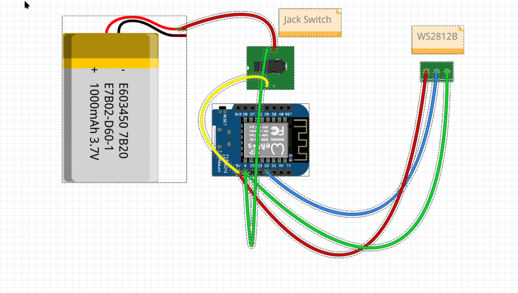
1. cIrcuit:
2. putting it together:
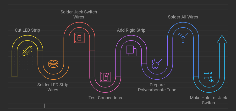
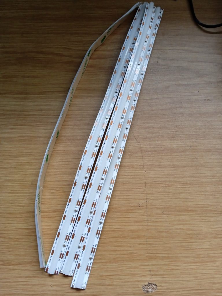
Cut the LED strip (here I am using 60px segments):
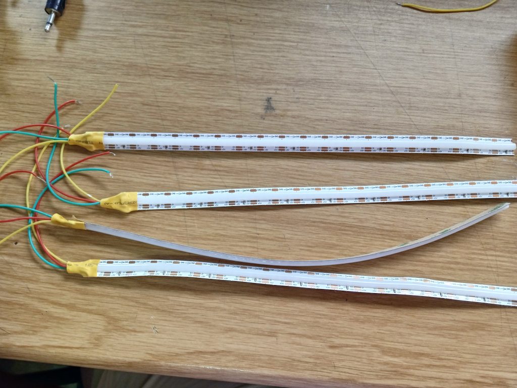
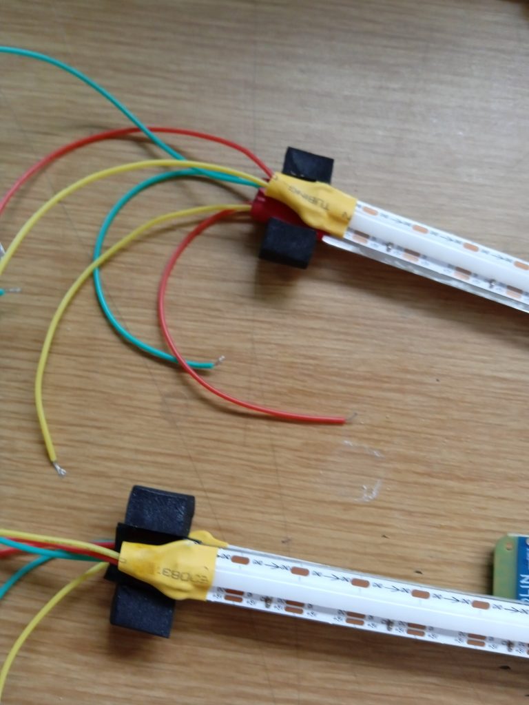
Solder the LED Strip wires (be sure to do it correctly, arrow points away from wire):
Solder the Jack Switch wires:
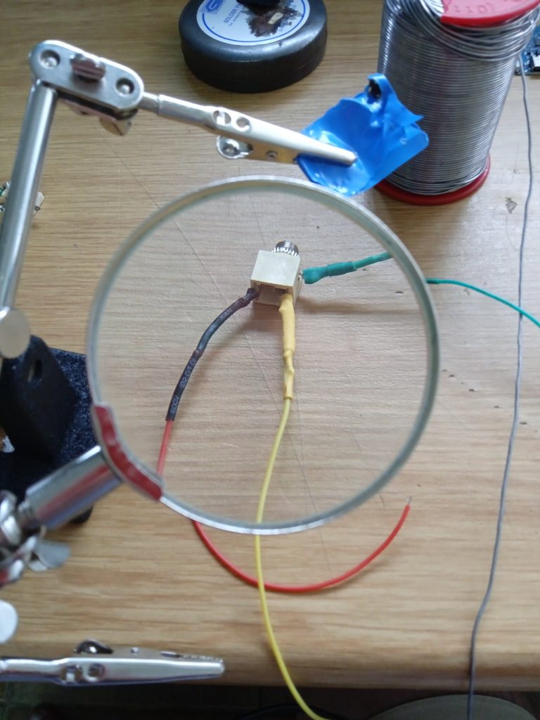
Test connections on Jack Switch (check with jack in for charging and out for on – red and yellow wires here are connecting battery with circuit when jack is not plugged in, but jack in connects charger to red wire only)
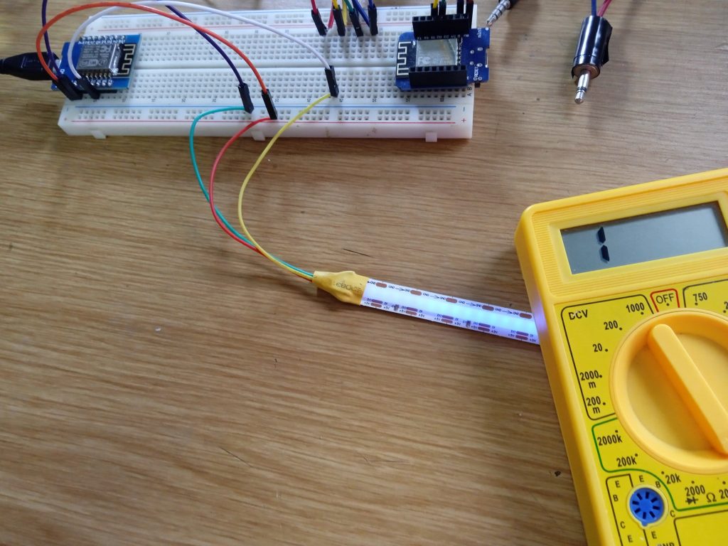
Test LED strip connections also:
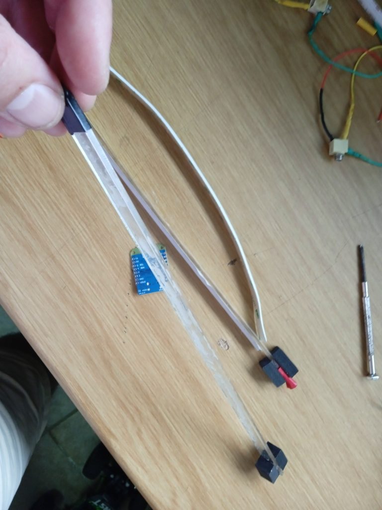
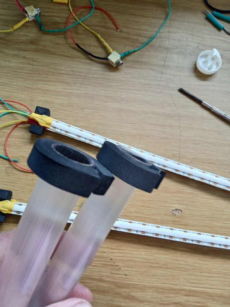
Add a rigid strip (I’m using perspex here) for backing to LED Strip. Also sticky backed rubber for spacing and shock absorbtion:
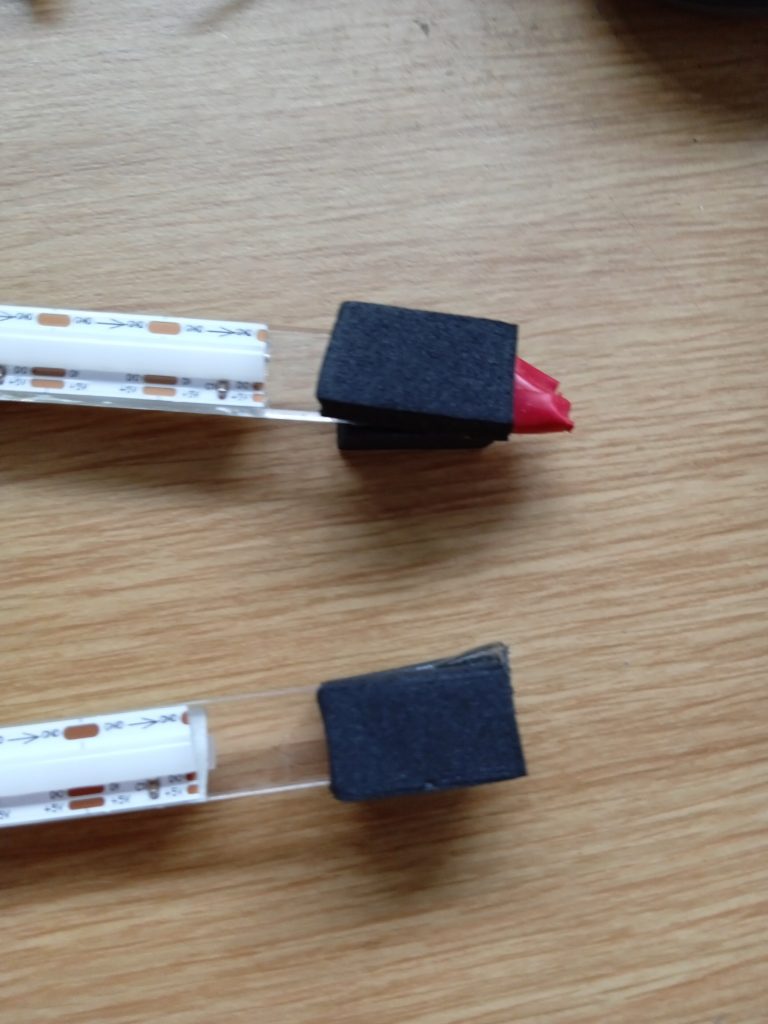
Example for rubber (I don’t have a link it’s from the local hardware):
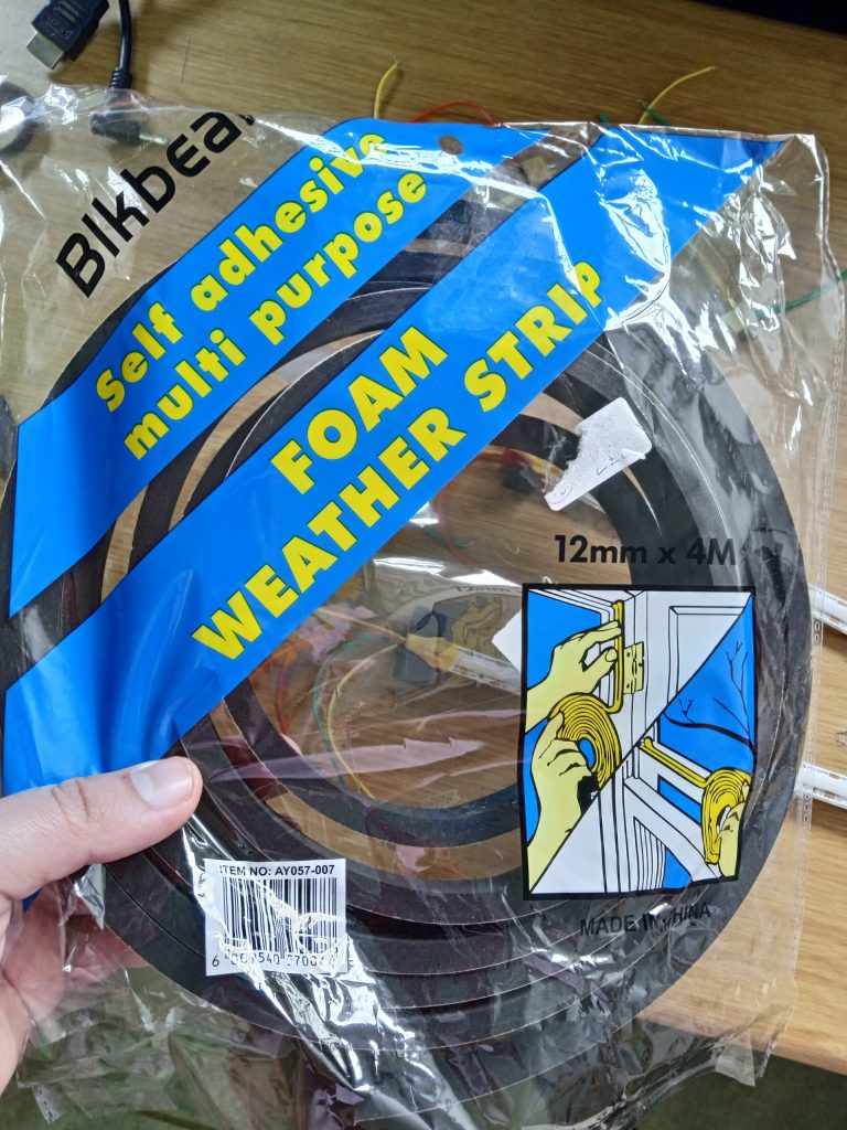
More rubber for the Polycarbonate Tube (I’m putting the circuit inside a plastic pipe) – not using the nice PC tube from Aliexpress here as mine hasn’t arrived yet:
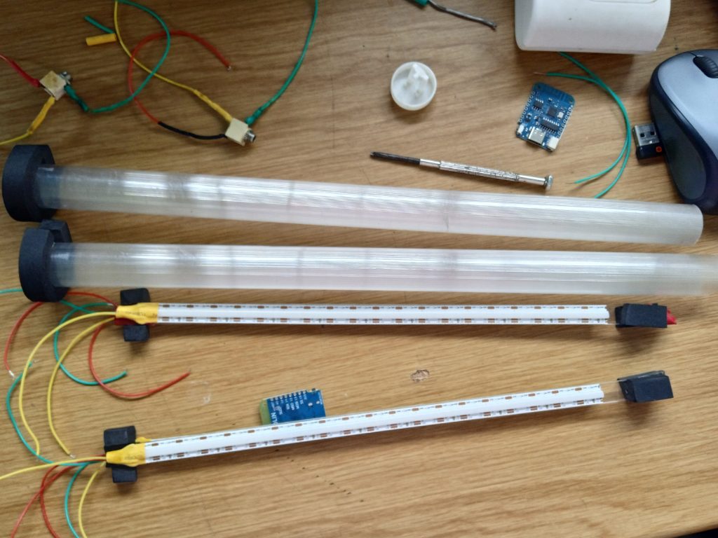
All set up and ready to put together:
Solder all wires (there are a lot!):
Make a hole for the jack switch (it has a screw on nut to secure it):
Put the circuit inside and fit the tube with LED strip. I used more rubber for keeping the circuit in place in the pipe, and screws to hold the PC tube in place:
SPIN:

Notes:
External charger circuit is here.
Works fine with APA102 as well, just add a wire from Clock to pin D1
Pins on the new Wemos boards are no longer labeled D1, D2 in Arduino IDE, just use 1 and 2..
The circuit diagram is simplified, you need 2 strips just wire them in paralell (GND-GND, 5v-5v, Data-Data)
Support the SmartPoi and Magic Poi projects on Patreon:
UPDATES:Sign up for our update alerts: